Part 1: Accessing Camera I/Os via Internal Connectors
In this first part, we explore how to interface with your camera’s digital inputs and outputs (I/Os) using internal hardware connections. There are two primary methods available for accessing these interfaces: through the built-in pin header or an external Hirose connector.
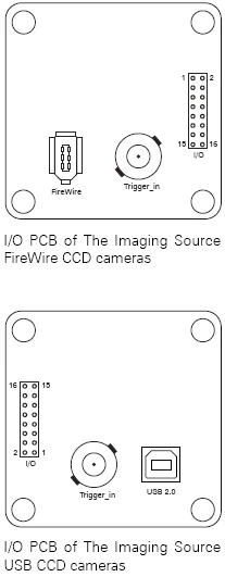
To utilize the internal pin header, you’ll need to access the backplane of the camera unit. As shown in the accompanying diagrams, there is a standard 2x8 pin configuration with a pitch measurement of 2.00mm between pins horizontally and vertically (i.e., 2.00 x 2.00 mm).
When preparing your custom cable assembly for these I/Os, be sure to consult the reference table provided below which details the specific wiring requirements.
Key Consideration: An important technical note regarding power delivery: FireWire camera models provide regulated +5V power through pins 3 and 4. This feature is not available with USB interface cameras where those same pins remain unpowered (open circuit).
This concludes Part 1 of our five-part series on camera I/O integration techniques.
Last Updated: 2025-09-05 02:12:15